Understanding Fragile Modular Facades
Fragile modular facades are common decorative and functional components in modern architecture, typically crafted from glass, thin metal sheets, or composite panels. While offering aesthetic appeal and lightweight properties, their material characteristics inherently limit their resistance to impact and deformation. During construction, key environmental and operational risks must be mitigated: Wind forces can cause facades to sway during hoisting, leading to collision damage; equipment vibrations may progressively weaken connection points, causing panels to loosen or crack; sudden temperature changes can induce internal stresses due to differing thermal expansion coefficients between materials, resulting in cracks or deformation. These risks require stringent control during operations.
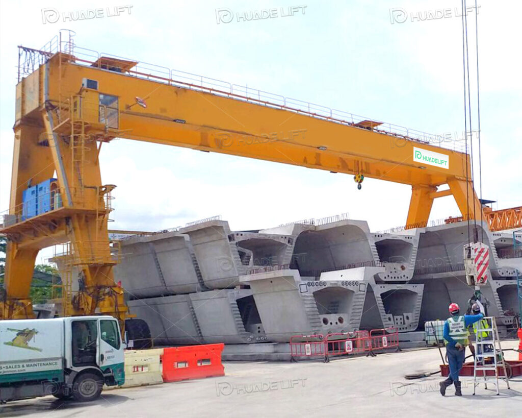
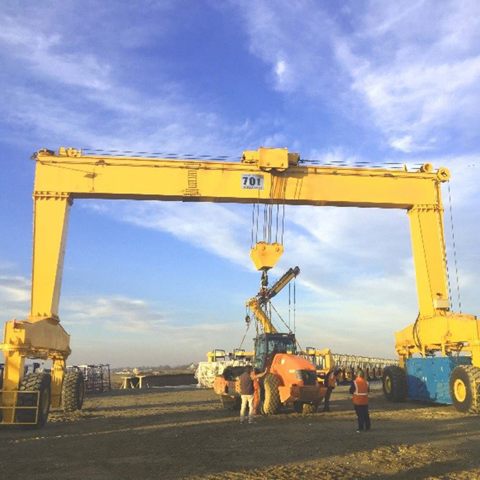
Why Rubber Tyre Gantry Cranes Are the Ideal Choice
Rubber Tyre Gantry (RTG) cranes offer distinct advantages when handling fragile modular facades. Their precise control enables slow lifting and fine adjustments, preventing impact damage from abrupt movements. Automated operation reduces human error and maintains load stability. In terms of load-bearing and mobility, they effortlessly handle large-scale, heavy facade components without frequent equipment changes. Additionally, these rubber tyre gantry cranes shorten installation cycles, reducing the risk of component damage from prolonged operations. They balance efficiency and safety, effectively controlling construction costs.
Pre-Lifting Planning and Preparation
Comprehensive pre-lifting planning is critical for ensuring the safety of fragile modular facades. This involves three key aspects: component characteristic assessment, lifting equipment selection, and path planning, laying the foundation for subsequent operations.
Facade Component Characteristic Assessment
Traceability and Verification of Weight Parameters
Component weight assessments must rely on official technical documentation provided by the manufacturer, not empirical estimates. Verify the total weight of all components—including the main body, frame, and connectors—to ensure compatibility with the rubber tyre gantry crane’s rated load capacity. For customized modifications, contact the manufacturer to update weight parameters, preventing rubber tyre gantry crane overload due to parameter discrepancies that could cause component deformation or safety incidents.
Dimensional Compatibility Analysis with Site Space
After measuring the component’s length, width, and height, conduct a compatibility analysis considering the construction site‘s spatial layout. For instance, in confined construction zones, verify whether the component can avoid fixed structures like walls and columns during horizontal movement. If traversing passageways, check clearance between protective barriers on both sides and the component to prevent scraping due to space constraints—especially critical for thin glass components where minor contact can cause surface damage.
Center of Gravity Shift Risk Assessment and Correction
If a component lacks a marked center of gravity, professional tools must simulate stress conditions to determine its center of gravity. For instance, a level can be used to test the fulcrum point when the component naturally balances. If a center of gravity shift is detected, it must be corrected by adjusting the lifting point position during sling attachment. This may involve adding auxiliary lifting points to distribute the load, preventing unilateral tilting after lifting due to center of gravity shift. Such tilting could cause weak panels to bear excessive pressure and fracture.
Lifting Equipment Selection
Material Compatibility of Slings with Component Surfaces
Prioritize material compatibility when selecting slings. For components with special coatings (e.g., anti-corrosion or decorative coatings) beyond glass and aluminum, use synthetic fiber slings with low friction coefficients to prevent coating abrasion. Simultaneously, inspect sling surfaces for burrs or cracks. Replace defective slings promptly to prevent surface scratches from damaged areas.
Alignment of Crossbars with Component Support Points
Crossbar support points must align with the component’s structural reinforcement, such as beams or columns within the frame. Avoid supporting crossbars on vulnerable areas of the panel. For curved or irregularly shaped components, custom curved cross-bars must be used to ensure full surface contact. This prevents localized stress concentration that could cause component deformation. Additionally, soft padding must be applied at all contact points between cross-bars and components to further protect surfaces.
Soft Strap Coverage and Fixing Method
Soft straps must cover all vulnerable areas of the component, including edges, corners, protruding decorative elements, and glass joints. Fixing should employ a wrapping method to avoid excessive localized pressure from single-point binding. Seamless connections without metal buckles must be used at strap joints to prevent scratches from metal buckles contacting the component. For components stacked in multiple layers, soft padding must be inserted between layers to prevent interlayer friction damage.
Lifting Path Planning
Anticipating and Avoiding Dynamic Obstacles
Beyond fixed obstacles, anticipate dynamic obstacles during construction, such as movement routes of other construction machinery and traffic frequency of material transport vehicles. Real-time operational data from the site dispatch system can be used to schedule lifts outside peak dynamic obstacle periods. Alternatively, temporary warning signs along the path can guide other equipment to avoid the lifting zone, preventing collisions caused by sudden intrusions of dynamic obstacles.
Layered Ground Bearing Capacity Testing
Ground stability checks must be conducted in layers: first, verify the ground bearing capacity at the crane parking point; second, assess the bearing capacity along the entire path. For backfilled areas or zones with dense underground utilities, specialized equipment should be used to test soil compaction. If compaction is insufficient, implement compaction treatment or lay multi-layer load-bearing pads to prevent localized ground subsidence during rubber tyre gantry crane movement, which could compromise component stability.
Real-Time Weather Monitoring and Response
Establish a real-time weather monitoring system to obtain wind speed, precipitation, and other weather updates via meteorological warning systems. If deteriorating weather is forecasted before lifting operations, adjust the work plan in advance and relocate components to indoor storage. If weather suddenly deteriorates during operations, immediately activate emergency protocols to safely lower components to designated secure storage areas, ceasing operations under adverse conditions.
Safe Lifting Techniques
Safe lifting techniques must adhere to standardized operating procedures while dynamically adjusting to site conditions. Ensure components remain stable throughout lifting to prevent damage from improper handling.
Step-by-Step Lifting Operations
Secondary Verification of Lifting Device Connections
After securing the component, conduct a secondary verification to check:
– Whether slings are firmly attached to lifting points
– Whether cross-bracing rods are level
– Whether soft pads cover all vulnerable areas Test tension by manually pulling the lifting gear and observe for any slight displacement of the component. If slack in the lifting gear or component shift is detected, re-adjust the securing before proceeding to the test lift phase to ensure all connection points meet safety requirements.
Fine-Tuning Strategy After Test Lift
During a test lift pause, if component tilt is detected, slowly lower the component first. Correct by adjusting the lifting point position or sling tension. Never force minor adjustments while the component is suspended to prevent damage from sudden stress changes. If uneven sling tension is observed, inspect for length discrepancies and replace with slings of consistent length as needed to ensure balanced loading.
Speed and Direction Control During Horizontal Movement
When moving components horizontally, maintain a constant speed and avoid sudden turns or acceleration. Operate the rubber tyre gantry crane using progressive controls, adjusting speed and direction through subtle lever movements. Simultaneously, ground personnel must provide real-time radio feedback on the distance between the component and obstacles to ensure it follows the predetermined path, preventing sway caused by abrupt maneuvers.
Addressing Environmental Challenges
Component Posture Control Under Wind Conditions
When wind strengthens, in addition to lowering the component height, assist in controlling its posture using guide ropes. Ground personnel must stand on either side of the component holding the guide ropes. They should slowly pull the ropes in the direction opposite to the sway to counteract wind forces and prevent excessive oscillation. Connection points between guide ropes and components must use soft materials to prevent surface damage from rope friction.
Emergency Adjustments for Uneven Ground
If the rubber tyre gantry crane shifts on uneven ground, first lower the component safely to the ground before inspecting the surface. Remove any local protrusions if present. For depressions, add load-bearing pads and reposition the rubber tyre gantry crane to achieve leveling. Conduct a test lift before resuming operations to confirm rubber tyre gantry crane stability, preventing recurring ground issues from compromising safety.
Collaborative Response to Sudden Obstacles
When unexpected obstacles enter the lifting path, the rubber tyre gantry crane operator must immediately halt movement and slowly lower the component. Simultaneously, the ground safety officer must swiftly direct the removal of the obstacle. Once the path is clear, re-inspect the route to confirm no other potential obstacles exist. Then, verify the component’s condition through a test lift to ensure it has not shifted or been damaged during the pause. Only then should lifting resume.
Transportation and On-Site Placement
The transportation and on-site placement of components are critical links connecting lifting and installation. Targeted measures must be implemented to prevent damage during transport, and precise placement techniques must ensure installation quality.
On-Site Safe Transportation
Adaptation of Transport Equipment
Before transporting components, adapt equipment such as flatbed trucks. For example:
– Install anti-slip rubber mats on the truck bed surface to increase friction between components and the bed.
– Add adjustable guardrails on both sides of the truck bed to prevent components from tilting sideways during transport. For taller components, install stabilizing supports on the vehicle roof to restrict vertical movement and prevent tipping due to excessive center of gravity.
Vibration Damping During Transport
In addition to placing soft materials between components and transport equipment, install shock absorbers on the vehicle undercarriage to reduce vibration transmission from road bumps. Maintain a constant speed during transport, avoiding sudden braking or sharp turns to prevent components from colliding with guardrails due to inertia. If the transport route includes continuous bumpy sections, plan alternative routes in advance or lay steel plates over the bumpy areas to reduce impact.
Real-Time Monitoring During Transport
Assign dedicated personnel to monitor the transport equipment in real time, observing the condition of the components. If minor displacement is detected, immediately stop the vehicle to adjust and secure the components. If soft cushioning materials become detached, reapply them before continuing transport. Monitors must carry emergency tools, such as spare soft straps and fastening bolts, to address unexpected situations promptly and ensure the safe arrival of components at their destination.
Transport Protection for Special Components
For exterior components with fragile attachments (e.g., embedded lighting fixtures, decorative glass elements), these attachments must undergo separate protective treatment prior to transport. For instance, wrap attachment surfaces with foam padding and secure them to the main component with adhesive tape to prevent detachment or impact damage during transit. Additionally, mark the packaging with “Fragile Attachments Location” to alert transport and unloading personnel to prioritize protection and prevent accidental contact during handling.
Precision Placement Techniques
Secondary Calibration of Alignment Markers
Before adjusting component positioning using pre-set alignment markers, calibrate marker accuracy. For instance, use a laser distance meter to verify the straightness of laser lines and a spirit level to check the horizontal alignment of chalk marks. If deviations are detected, reapply the markers to ensure perfect correspondence with the frame’s installation holes and positioning points. When adjusting component placement, confirm alignment accuracy from multiple angles to avoid positional errors caused by single-perspective observation.
Synchronized Coordination During Lowering
When lowering components, the rubber tyre gantry crane operator must maintain close coordination with ground guides. Guides provide real-time feedback on the distance between the component and the frame via hand signals or walkie-talkies, allowing the operator to fine-tune the lowering speed and direction accordingly. As the component nears the frame, reduce the lowering speed to ensure smooth contact between the component edge and the frame. Avoid collisions caused by excessive speed, which could compromise installation sealing integrity.
Post-Fixing Seal Integrity Inspection
After component fixation, inspect the connection points between the component and the frame for proper sealing. Verify that sealant strips are properly seated and that gaps are uniform. If sealant strips are misaligned, reposition and refasten the component. If gaps are uneven, verify that fasteners are secure and adjust torque as necessary to ensure tight contact between the component and frame, preventing future water or air leakage.
Post-Installation Component Integrity Inspection
After placement and securing, conduct a comprehensive integrity inspection. First, inspect the component surface for new scratches, cracks, or dents, focusing on edges, corners, and vulnerable panel areas. Second, verify that all fasteners are present and securely tightened, confirming no loose or missing fasteners. Finally, test the connection strength between the component and frame by applying slight external force to the component and observing for displacement, ensuring stable installation. Maintain detailed records during inspection, addressing any issues promptly to prevent latent quality hazards.
Conclusion
When handling fragile modular facades with rubber tyre gantry cranes, adhere to the core principles of “prevention first and precision operation.” From pre-lifting component assessment, lifting device selection, and path planning; to step-by-step execution and environmental adaptation during lifting; to meticulous control of transportation and placement details; and subsequent construction coordination and protection—each phase must strictly adhere to professional standards. This fully leverages the rubber tyre gantry crane’s precision and stability advantages to minimize component damage risks, ensure construction safety and quality, and provide reliable technical support for building facade construction.