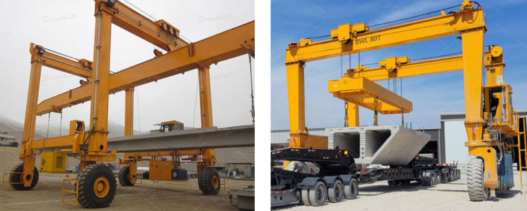
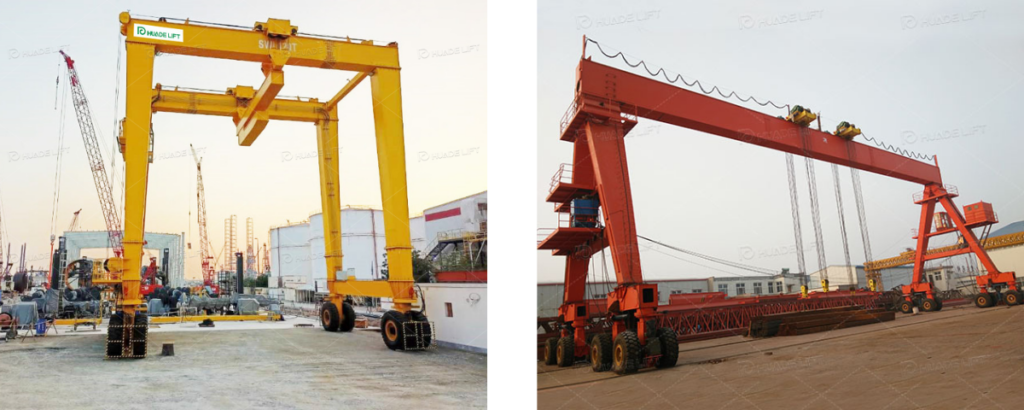
Overview of Rubber Tyred Gantry Crane Structure
The RTG crane structural system comprises the gantry frame, outrigger wheel assembly, hoisting trolley and lifting device, main girder, travel mechanism, steering drive system, and power system. These components work in concert to perform heavy-load lifting, lateral movement, and other operations while ensuring operational stability.
This system must bear loads of tens of tons, withstand dynamic stresses, and maintain stable precision in outdoor environments. The rationality of structural component design, connection reliability, and overall coordination form the core foundation of its performance.
Key Factors Affecting Rubber Tyred Gantry Crane Stability
Stability is the core safety metric for RTG cranes. Structural factors influencing stability permeate key components such as the main frame, counterweight system, and wheel sets. These factors interact to form a comprehensive stability assurance system.
Main Beam, Frame, and Outrigger Structure
The main beam, frame, and outriggers form the primary load-bearing structure of the RTG crane, serving as the core for load transfer. Their design quality directly determines the equipment’s load-bearing capacity and deformation resistance. Whether during static lifting or dynamic operation, effective force transmission and distribution rely on this structural system.
Main Girder Design and Load Capacity
The main girder bears the load of the hoisted object, the trolley’s self-weight, and dynamic loads. Its design focuses on section shape, material selection, and stiffness. A box-type section reduces weight while enhancing bending and torsional resistance. High-strength steel increases the load-bearing limit, and sufficient stiffness prevents excessive deflection that could compromise operational precision.
Welding quality at girder joints is critical, requiring strict control of weld defects to prevent stress concentration and fatigue failure.
Frame Torsional Stiffness and Overall Structural Strength
The gantry frame connects the girders to the legs, experiencing torsional forces during slewing, traversing, or off-center loading. Insufficient stiffness can cause deformation, vibration, and reduced accuracy. Its torsional stiffness and strength directly impact stability under complex operating conditions.
To enhance frame performance, adopt box-type rigid-jointed structures. Increase sectional area, optimize node connections, and incorporate stiffeners to improve deformation resistance. Simultaneously, optimize connections with the main beam and outriggers to ensure uniform load transfer and prevent stress concentration.
Geometric Shape and Force Distribution Characteristics of Outriggers
Outriggers transfer equipment weight and loads to the ground. Proper spacing expands the support base to enhance stability against overturning. Rectangular or trapezoidal cross-sections improve bending and compression resistance, preventing buckling deformation under vertical loads.
Horizontally, outriggers must resist lateral displacement caused by inertial forces and wind loads. This can be achieved by increasing the section’s moment of inertia, installing diagonal braces, or adding reinforcement plates. These measures ensure horizontal forces are evenly distributed to the wheel assembly and ground, preventing localized overloading.
Structural Balance and Center of Gravity Optimization
Structural balance and center of gravity position directly impact the static and dynamic stability of RTG cranes. Center of gravity displacement poses the primary risk of overturning. Optimizing the center of gravity through structural design and maintaining dynamic equilibrium are key to enhancing stability.
Machine Room and Hoisting System Layout
The machine room and hoisting system constitute the primary weight concentration zones. Design must adhere to the principles of “symmetrical layout and balanced counterweighting.” Heavy components such as hoisting drums should be positioned at the center of the main beam or symmetrical locations.
The machine room placement must balance power transmission requirements with center of gravity equilibrium, ensuring controllable shifts in the center of gravity. Machine room protective structures should utilize lightweight materials and compact layouts to minimize weight impact on center of gravity balance.
Optimization of Main Beam and Outrigger Weight Ratio
The weight ratio between the main beam and outriggers directly affects center-of-gravity distribution: an overly heavy main beam elevates the upper center of gravity, while excessively heavy outriggers increase equipment weight and energy consumption. Mechanical calculations must optimize this ratio.
Design requires mechanical calculation optimization: the main beam employs high-strength materials to reduce weight, while outriggers control weight through rational cross-section and material selection. This achieves optimal center-of-gravity balance, balancing stability and economy.
Dynamic Balance During Acceleration, Braking, and Steering
Inertial forces generated during acceleration, braking, and steering cause momentary shifts in the center of gravity. Design must employ variable frequency speed control for smooth operation. Buffer devices at the main beam-trolley connection absorb vibrations, while the steering mechanism ensures synchronized wheel rotation, minimizing lateral forces and outrigger torque.
Wheel System and Travel Mechanics
The wheel system is the sole point of contact between the RTG crane and the ground. Its configuration, operating mechanism, and tire performance directly influence load distribution, operational stability, and ground adaptability.
Wheel Configuration and Load Distribution
Wheel configuration determines load distribution effectiveness. Different numbers and arrangements of wheels affect axle load distribution and ground bearing capacity, which in turn relate to operational stability and ground adaptability.
Comparison of 4-Wheel, 6-Wheel, 8-Wheel, and 16-Wheel Configurations
The 4-wheel configuration suits small-tonnage light-duty applications. 6-8 wheel configurations are suitable for medium-tonnage routine operations. The 16-wheel configuration is ideal for heavy-tonnage or poor ground conditions. Wheel arrangement must ensure balanced force distribution to prevent localized overload.
Axle Load Distribution and Ground Bearing Capacity
Uneven axle load distribution accelerates wheel system wear and ground settlement. Design must optimize wheel layout and employ balanced suspension systems for rational load allocation, while establishing maximum axle load limits based on site standards.
Operational and Steering Structural Dynamics
The dynamic characteristics of operational and steering structures determine the stability, maneuverability, and structural impact during RTG crane movement. This directly affects the equipment’s ability to maintain a stable posture under complex operational paths and profoundly influences the stress state and service life of structural components. Rational dynamic design effectively reduces operational energy consumption and minimizes additional wear on the ground and the structure itself.
Steering System Structure and Turning Radius
All-wheel steering enables compact turning radii for enhanced agility. Half-wheel steering features simpler structures, where steering mechanisms must ensure rigidity and reliability to guarantee precise steering, prevent wheel slip/tire damage, and mitigate lateral force impacts.
Frame Design and Driving Stability Correlation
Frame stiffness, strength, and wheel-frame connection methods influence vibration resistance and roll control. Impacts from uneven surfaces, if not effectively absorbed, can trigger resonance and structural fatigue.
Design requires synergistic optimization of the frame and drivetrain system. Enhancing frame torsional stiffness and employing elastic suspension systems to absorb vibrations ensures reliable connections and smooth load transfer, thereby improving driving stability.
Structural Constraints on Travel Speed and Maneuverability
Increased travel speed amplifies inertial forces, demanding higher structural load-bearing capacity. Maneuverability is constrained by steering systems, wheel configurations, and equipment dimensions, necessitating parameter determination within safety limits.
Design must integrate operational requirements to establish parameters within permissible structural load limits. By optimizing steering mechanisms, enhancing rigidity, and employing efficient braking systems, operational efficiency can be improved while maintaining safety.
Tire Structure and Material Selection
Tires make direct contact with the ground, and their structure and material properties influence driving stability, load-bearing capacity, service life, and cost.
Tire Dimensions, Materials, and Heat Resistance
Tire dimensions must match the wheel assembly and axle load. Port operation tires require high-strength, high-abrasion-resistant, heat-resistant rubber compounds and multi-ply cord structures to enhance load-bearing and tear resistance.
Heat generation must be minimized through heat dissipation structures, heat-resistant formulations, and proper control of operating parameters to prevent aging, blowouts, and extend service life.
Tire-Ground Friction and Stability Impact
Tire-ground friction forms the operational foundation, ensuring traction, braking effectiveness, and steering safety. Sufficient friction prevents operational loss of control.
Friction depends on tread pattern, material adhesion, and ground pressure. Tread patterns must be optimized for ground conditions, while uniform ground pressure is achieved through proper axle load distribution. Worn tires should be replaced regularly.
Hoisting, Trolley, and Load Handling Structures
The hoisting, trolley, and load handling structure constitutes the core system enabling the RTG crane to lift and traverse heavy loads. Its design determines operational efficiency, load control precision, and structural safety.
Hoisting Mechanism Structural Design
As the primary load-bearing component, the hoisting mechanism must balance load capacity, power transmission efficiency, and operational safety to ensure smooth and precise lifting. Particular emphasis is placed on effectively suppressing load impact and structural vibration during heavy-load starts/stops and boom swing operations.
Hoist Drum Arrangement, Rope Path, and Stress Distribution
Hoist drum placement must prevent wire rope interference, with dimensions matching rope diameter and lifting capacity. Rope path design ensures even rope lay to minimize wear and torsional impact.
Optimized drum structure achieves uniform stress distribution. Wire rope tensioning and anti-jump devices are installed to guarantee operational safety.
Trolley Rail Stiffness and Main Beam Structural Synergy
The stiffness of trolley rails and their synergy with the main beam affect operational smoothness. Insufficient rail stiffness can cause deformation and stalling, while poor synergy leads to uneven load transfer, accelerating structural wear.
High-strength rail materials and reliable fastening methods must be employed. Synergistic optimization between rails and main beams ensures coordinated deformation and uniform load transfer.
Interaction Between Lifting Device System and Crane Frame
Additional loads generated by swaying and tilting of the lifting device impact the main beam and frame, affecting equipment safety and operational precision. Structural design must optimize their interaction.
Install buffer devices between the lifting device and hoisting mechanism, optimize the suspension method and wire rope tension distribution of the lifting device, and adopt lightweight design for the lifting device to reduce additional loads.
Anti-Sway and Anti-Tilt Structural Systems
Swinging and skewing of the lifting device and load are primary issues affecting operational efficiency and safety. Anti-sway and anti-skew systems control load movement through mechanical or electronic means to enhance equipment performance.
Impact of Anti-Sway Systems on Structural Loads
A well-designed anti-sway system reduces impact damage to structures caused by load swinging. Appropriate mechanical or electronic anti-sway methods must be selected based on lifting capacity and operating speed to ensure load controllability and structural safety.
Structural Requirements for Anti-Sway (Offset Correction)
Anti-sway systems require structural support: trolley travel mechanisms must ensure synchronization, main girder rails must guarantee straightness and installation accuracy, and lifting device suspension structures must allow adjustment margins to control and correct sway at the source.
Sensor-Based Structural Health Monitoring
Sensor health monitoring systems install sensing devices at critical structural points to collect real-time data and provide early warnings of anomalies, serving as a basis for maintenance. These systems require deep integration with structural design and coordinated control systems.
The system must be deeply integrated with structural design to ensure proper sensor placement and accurate data collection. It should also interface with equipment control systems to enhance intelligent operation and maintenance capabilities.
Power System Integration and Its Structural Influence
The power system supplies energy to the RTG crane. Its type and integration method impact energy consumption and environmental performance while influencing structural layout, weight distribution, and vibration control. Structural integration requirements for different power systems are as follows:

Diesel-Electric System
Diesel generators must be symmetrically arranged to balance the equipment’s center of gravity. Vibration damping devices should be installed to reduce operational impact on the structure. Additionally, rational heat dissipation channels must be designed to maintain stable generator operating temperatures, preventing high temperatures from affecting structural material performance.
Pure Electric System
Cable reels must be integrated into the gantry frame or outrigger structure to ensure convenient cable retrieval/retraction without interference risks. Core electrical equipment like control cabinets should be positioned considering weight balance and maintenance accessibility, avoiding adverse effects on overall center-of-gravity distribution.
Hybrid Power System
Battery packs should prioritize bottom placement to lower the equipment’s center of gravity and enhance stability. Battery protection structures must incorporate fireproofing, waterproofing, and shock resistance. The strength of their mounting frames must match the battery weight and vibration loads during operation to ensure structural safety.
General Design Requirements
All power systems must reserve sufficient maintenance access and operational space, with safety-compliant protective facilities installed. Strictly control the weight of power system accessories to prevent additional loads from compromising the crane’s overall structural balance.
Materials, Fabrication Quality, and Environmental Factors
The structural performance of RTG cranes depends on design, materials, and manufacturing quality, while also being influenced by the complex outdoor port environment. These factors collectively determine the equipment’s long-term reliability.
Impact of Materials and Manufacturing on Strength
Materials form the foundation of structural strength, while manufacturing quality ensures optimal material performance. Together, they determine the structure’s load-bearing capacity and durability. Only by combining premium materials with sophisticated manufacturing techniques can cranes maintain stable and reliable performance during prolonged heavy-duty operations.
High-Strength Steel Selection and Welding Quality
High-strength steel enhances structural strength while reducing self-weight. Steel grades must be selected based on load characteristics—such as main girder bending and outrigger compression—to balance strength and toughness, preventing brittle fracture or excessive deformation.
Welding quality determines structural reliability. Strict control of welding processes is essential, involving material-matched parameters and non-destructive testing to ensure weld integrity. Heat treatment of the welded joint’s heat-affected zone eliminates residual stresses.
Fatigue-Resistant Design and Long-Term Durability
RTG cranes are susceptible to fatigue damage from cyclic dynamic loads. Nodes must be optimized to prevent stress concentration, high-fatigue-strength steels selected, and fatigue performance enhanced through surface treatments.
Simultaneously, fatigue life calculations provide maintenance guidelines, ensuring safe operation throughout the design service life.
Corrosion Protection and Structural Lifespan
Environments with high humidity and salt spray accelerate structural corrosion, weakening strength and shortening lifespan. Corrosion prevention is a critical aspect of design and manufacturing.
Implement corrosion control measures such as sandblasting for rust removal and painting, hot-dip galvanizing for fasteners, and cathodic protection. Structural design should eliminate painting and drainage dead zones to facilitate corrosion prevention construction and maintenance.
Environmental Impact on Structural Performance
Environmental factors like wind, ground conditions, and temperature affect structural loading and performance. Designs must fully account for these elements to ensure equipment adapts to diverse environments. This involves creating comprehensive environmental adaptation solutions—from structural strength and material selection to protective measures.
Wind Load Requirements and Reinforcement Design
Wind load represents the primary external threat. Calculate wind loads based on regional standards, reinforce structures with wind-resistant tie rods, and install wind anchoring devices to ensure safety during high winds.
Ground Hardness and Leveling Requirements
Insufficient ground hardness may cause settlement, while significant leveling deviations increase leg bending moments. Clearly define ground requirements in design, enhance adaptability through multi-stage configurations and adjustable legs, and perform regular ground maintenance during operation.
Impact of Temperature and Climate on Material Performance
Temperature and climate affect material properties. High temperatures can cause steel strength degradation and rubber component aging, while low temperatures may reduce metal toughness, leading to brittle fracture. Select temperature-resistant and corrosion-resistant materials accordingly, optimize heat dissipation design, and specify operational requirements for different climates in the maintenance manual.
Structural Safety Standards and Testing Requirements
Structural safety standards serve as the basis for design and manufacturing. Rigorous testing and validation ensure equipment compliance, with both elements collectively forming a safety assurance system.
Structural Standards and Compliance
RTG crane structural design must comply with international and industry safety standards to ensure compliance throughout design, manufacturing, and operation, safeguarding personnel and equipment.
Structural Design Requirements per ISO, FEM, etc.
ISO and FEM standards serve as primary design references, specifying requirements for static/dynamic load safety factors, fatigue design, etc. Designs must comply with both international and regional standards to mitigate safety and economic risks.
Redundant Design and Fail-Safe Structural Principles
Redundant design achieves load sharing through backup critical components (e.g., multiple wire rope load-bearing systems). Fail-safe principles ensure safe load transfer upon single-component failure, enhancing safety redundancy.
Verification and Testing
Testing validates design rationality and manufacturing quality. Static and dynamic tests ensure structural performance compliance, providing data support for safe operation. This process not only identifies design oversights and manufacturing defects promptly but also delivers precise basis for subsequent structural optimization and upgrades.
Static Load, Dynamic Load, and Stability Testing
Static load testing applies 1.25 times the rated load to verify structural stability. Dynamic load testing validates impact resistance at 1.1 times the rated dynamic load. Stability testing assesses overturn resistance under extreme conditions. All tests must be conducted per standards with recorded and analyzed data.
Fatigue Testing and Long-Term Performance Validation
Fatigue testing evaluates fatigue resistance through accelerated cyclic load simulation, while long-term performance validation tracks structural changes via operational monitoring. This provides a basis for maintenance, lifespan assessment, and design optimization.
Conclusion
The stability and performance of RTG cranes depend on scientifically designed structures. This paper analyzes key influencing factors from multiple dimensions, including main structure, working mechanisms, material manufacturing, and environmental adaptability. Through the interaction of these factors, the structural performance of RTG cranes will be further enhanced.