What Is a Rubber Tyred Gantry Crane
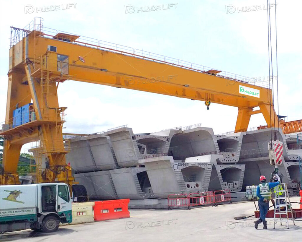
Rubber tyred gantry cranes are gantry cranes that move on rubber wheels. Unlike rail-mounted models, they offer highly flexible mobility, capable of traversing multiple work aisles to load, unload, stack, and transfer goods, adapting to dynamically changing storage environments. Their structure primarily consists of two sets of main legs supporting rubber wheels, a horizontal main girder connecting the legs, a hoisting mechanism or trolley running along the girder, and lifting attachments or hooks for cargo handling. These components work in concert to achieve precise movement and positioning of heavy loads.
Why Proper Installation of a Rubber Tyred Gantry Crane Matters
Correct installation of rubber tyred gantry cranes is the core prerequisite for ensuring safe equipment operation. These cranes handle substantial loads during operation. Installation oversights can compromise structural stability, leading to component loosening or displacement during tasks. This not only disrupts normal operations but also risks safety incidents, threatening personnel and surrounding facilities. Only standardized installation—ensuring precise alignment and secure connections of all structural components—can establish a foundation for safe operation.
Proper installation also directly impacts the overall operational efficiency of the worksite. Installation issues necessitating shutdowns for rectification not only delay equipment commissioning but may disrupt production schedules, hindering the entire operational rhythm. Standardized installation ensures equipment passes commissioning tests on the first attempt and enters service smoothly, safeguarding the continuity of worksite operations and preventing operational losses caused by installation flaws.
Key Factors Affecting Installation
Crane Characteristics
The size and functional complexity of a crane directly impact installation efficiency. Larger cranes feature heavier and more voluminous structural components, requiring more intricate handling procedures and greater manpower coordination during component transport, hoisting, and assembly, thereby extending installation time. Cranes equipped with specialized functions such as automated controls, remote operation, or anti-sway systems necessitate additional parameter tuning and system integration during installation, further increasing complexity and prolonging the timeline.
Site Conditions
The condition and environment of the installation site can disrupt progress. Insufficient ground leveling or weak load-bearing capacity necessitates preliminary ground preparation such as grading and reinforcement, consuming extra time and preventing timely installation commencement. Inadequate drainage systems may cause water accumulation during rainfall, compromising equipment operation and personnel safety, requiring installation suspension and resulting in delays.
Logistics and Transportation Efficiency
Component transportation is critical to installation timelines. Crane parts are often large, heavy components requiring coordinated vehicle dispatch and route planning. Traffic congestion or road restrictions can prevent timely delivery, halting installation until components arrive. Improper handling or securing during loading/unloading may damage parts, necessitating re-scheduling and further delays.
Customization and Functional Configuration
Custom designs and additional features extend installation duration. To meet specific requirements, some cranes undergo structural modifications or incorporate specialized components. These customized parts require distinct installation procedures from standard components. Optional features like hydraulic steering or advanced control systems necessitate separate installation and debugging, prolonging overall installation time.
Essential Preparations Before Installation
Assessing the Work Environment and Requirements
A comprehensive evaluation of the crane’s operating environment and operational requirements before installation is fundamental to ensuring smooth subsequent installation and operation. This assessment should cover three dimensions: ground conditions, environmental characteristics, and logistics/transportation.
Ground Condition Assessment
The operating surface must meet dual requirements for levelness and load-bearing capacity. Sufficient levelness prevents body sway and uneven wheel loading during crane operation, reducing abnormal tire wear and ensuring operational stability. Adequate load-bearing capacity must support both the crane’s own weight and operational loads, preventing ground settlement or collapse due to insufficient support that could cause equipment tilting.
Simultaneously, a clear layout of the operational area must be planned, defining crane travel routes, cargo stacking zones, and turning spaces. A rational layout minimizes unnecessary crane movement during operations, enhancing efficiency while ensuring sufficient maneuvering space to prevent collisions with surrounding structures or facilities.
Environmental Considerations
Thorough understanding of the site’s climate and environmental characteristics is essential. In areas with frequent precipitation, advance improvements to the site drainage system are essential. Install drainage facilities to prevent rainwater accumulation on the ground, avoiding waterlogging that could soak crane tires or corrode electrical components, thereby affecting equipment performance and lifespan. For dusty or sandy environments, establish a regular ground maintenance plan to promptly clear debris and dust. This ensures proper wheel-to-ground contact, maintains stable traction, and guarantees normal crane movement and operation.
Logistics and Traffic Planning
Ensure the rationality of transportation routes and operational spaces. Guarantee that vehicles transporting crane components and installation equipment can access the site smoothly. Plan dedicated driving routes and parking areas to prevent interference between transport vehicles and on-site personnel/equipment. Simultaneously, reserve sufficient installation space to provide a safe and convenient environment for assembling components and debugging systems, avoiding delays or quality issues due to spatial constraints.
Reviewing Design and Technical Documentation
Design and technical documentation serve as the core guidance for installation work. Thorough review is essential to ensure equipment compatibility, compliance, and safety, covering three key aspects: document completeness verification, parameter compatibility confirmation, and standard compliance validation.
Document Completeness Verification
Comprehensively cross-reference crane design drawings with manufacturer-provided technical documentation, including structural layout diagrams, electrical schematics, hydraulic system diagrams, and control system configuration specifications. Focus on verifying whether documentation is complete and clearly articulated, identifying any ambiguous or contradictory content. This ensures installers accurately comprehend equipment structure and installation requirements, preventing installation errors due to missing or ambiguous documentation.
Parameter Compatibility Confirmation
During review, prioritize confirming the alignment of equipment component parameters with actual operational requirements. Verify that component dimensions, connection methods, and performance metrics align with the on-site operational environment. For example, assess whether the main beam structure accommodates the worksite span and whether the hoisting mechanism’s capacity meets cargo weight requirements. Additionally, thoroughly examine documentation related to the crane’s load characteristics and duty cycle to understand its load-bearing capacity and operational cycles under various working conditions. This ensures the equipment’s duty cycle corresponds to the intensity and frequency of on-site operations, preventing overloading or underutilization due to parameter mismatches.
Verification of Standard Compliance
Confirm whether the equipment meets local engineering construction standards and safety regulations. Compliance must be verified across all aspects—from mechanical structural strength and electrical system safety protections to operational noise levels and environmental emission standards—to prevent situations where the equipment cannot be put into service after installation due to non-compliance, or faces risks of rectification or shutdown during subsequent operation. If technical questions or uncertainties arise during review, promptly communicate with manufacturers and suppliers to clarify details and resolve concerns, ensuring installation proceeds under accurate technical guidance.
Preparing Foundations or Working Surfaces
Although rubber tyred gantry cranes do not require rail support, the quality of the working surface directly impacts operational safety and equipment lifespan. Preparation involves three key measures: professional site surveys, ground treatment, and auxiliary facility improvements.
Ground Load-Bearing Capacity Survey
Engage a professional agency to conduct a geological survey of the operating ground to determine its actual load-bearing capacity. Focus on confirming whether the ground can withstand the crane’s static weight when stationary and the dynamic loads transmitted by the wheels during operation. This prevents safety incidents such as crane tilting or component damage caused by ground collapse or cracking due to insufficient load-bearing capacity, and provides data support for subsequent ground treatment.
Ground Leveling Treatment
Ground levelness is critical for stable equipment operation. Professional equipment must be used to level the work surface, eliminating unevenness such as bumps and depressions. Substandard ground levelness causes crane body tilting during operation, uneven stress distribution across structural components, accelerated wear on wheels and metal parts, and potential impairment of hoisting mechanism positioning accuracy, thereby reducing operational efficiency. Employ specialized leveling techniques to ensure ground flatness meets technical requirements for equipment installation and operation.
Comprehensive Auxiliary Facilities
Comprehensive ground markings and drainage systems must be provided. Clearly mark crane travel paths, turning zones, and cargo stacking boundaries on the ground to help operators accurately grasp the operational scope. This prevents equipment from exceeding designated areas due to operational errors and colliding with surrounding facilities. Markings also serve as a basis for subsequent ground maintenance and operational management, enhancing standardized site management.
Drainage system design must integrate site topography and precipitation patterns. Install drainage channels and adjust ground slopes to ensure rapid, unimpeded water runoff, preventing surface pooling. Standing water not only reduces ground load-bearing capacity but may also infiltrate crane electrical and hydraulic systems, causing short circuits, component corrosion, and other failures. Thus, a comprehensive drainage system is fundamental to ensuring long-term, stable equipment operation. For concrete or asphalt surfaces, compressive strength and flexural strength must be tested to ensure the material properties meet the long-term operational demands of the equipment, preventing cracks or damage due to insufficient material strength.
Ensuring Power Supply and Electrical Readiness
The power supply and electrical systems form the operational core of the crane. Advance preparation of infrastructure, circuit planning, safety protections, and system commissioning is essential to guarantee safe and stable electrical operation. This encompasses four key phases: power facility preparation, cable routing planning, safety protection setup, and control system inspection.
Power Supply Facility Preparation
Appropriate power infrastructure must be established in advance based on the crane’s power supply method. First, verify power system parameters—including voltage, frequency, and current capacity—to ensure full compatibility with the crane’s electrical requirements, preventing component burnout or startup failure due to mismatched specifications. If diesel generators are used, inspect generator performance and test output stability beforehand. If relying on grid power, verify the circuit’s load capacity to ensure it can handle the crane’s maximum power consumption during operation, preventing issues like tripping or overheating due to circuit overload.
Cable Routing Planning
Cable layout must be designed considering the crane’s operational path and working range to prevent entanglement, dragging, or wear during operation. Properly install auxiliary equipment such as cable supports and cable reels to ensure cables can freely extend, retract, and adjust tension as the crane moves, maintaining appropriate tension and avoiding friction with moving equipment components. When selecting cables, choose types with excellent insulation, wear resistance, and corrosion resistance based on electrical parameters and the operating environment. This prevents electrical leakage accidents caused by damaged cable jackets, ensuring the electrical system’s safety and durability.
Safety Protection Setup
The grounding and neutral connection protection system is the core safeguard for electrical safety. Reliable grounding devices must be installed strictly according to safety standards. Effectively connect the crane’s metal structure and the metal casings of electrical equipment to the earth to ensure that leakage currents are rapidly diverted to ground in the event of an electrical fault, preventing electric shock accidents. Conduct regular ground resistance testing to ensure compliance with safety standards, guaranteeing effective grounding protection and eliminating safety hazards caused by poor grounding.
Control System Inspection
Perform comprehensive pre-operation inspections and tests on the crane’s control system. Verify the integrity of control devices, instruments, and communication equipment within the control cabin, ensuring normal functionality of buttons, switches, displays, and other components. Simultaneously, test communication links between the crane control system and the site management system/remote operation platform to confirm accurate data transmission and smooth command execution, ensuring readiness for subsequent automated operations and remote monitoring. Additionally, perform insulation testing and circuit continuity checks on the electrical system to identify potential faults, guaranteeing safe startup and stable operation after installation.
Steps for Installing a rubber tyre gantry crane
Preparation and Planning
Prior to formal installation, prepare equipment, tools, and safety measures. Gather new tires compatible with the crane, hydraulic jacks and supports for lifting, various wrenches, torque wrenches, tire pressure gauges, lubricants, and sealants. Simultaneously, prepare safety equipment including protective gloves, hard hats, and safety goggles.
Conduct specialized safety training to ensure personnel are familiar with the crane’s structure, installation procedures, and safety protocols, clearly defining roles and responsibilities. Clear debris from the work area, establish safety warning signs to demarcate the work zone, inspect ground stability and tool/equipment performance to ensure installation safety.
Tire Removal
Move the crane to a flat, stable area with sufficient load-bearing capacity. After parking securely, engage the parking brake and shut off the engine to prevent accidental movement.
Before lifting, inspect the hydraulic jack’s performance. Position it at designated support points according to the structural design. Raise the crane slowly while monitoring balance. Once the tire is off the ground, immediately secure the crane with jack stands to prevent risks from jack failure. When removing the old tire, gradually loosen the hub fasteners with a wrench to avoid damaging components from excessive force. Then, work together to remove the old tire and store it as required for disposal.
New Tire Installation
Before installation, thoroughly inspect the wheel hub for surface cracks, deformation, or wear. Verify the integrity of bolts and threads; address any damage promptly. Clean the hub surface of dust, oil residue, and rust to ensure proper adhesion.
Align the new tire with the hub according to the manufacturer’s instructions, ensuring correct installation orientation. Slowly position the tire onto the hub and adjust it to precisely align the bolt holes with the bolts. When installing the fasteners, manually screw each one in individually to prevent thread misalignment. After initial tightening, use a torque wrench to secure them symmetrically at the specified torque to ensure even force distribution, preventing hub deformation or tire misalignment.
Final Adjustment and Inspection
After installing the new tires, activate the hydraulic jack to slowly raise the crane. Remove the support brackets and gradually lower the equipment. Closely monitor tire contact with the ground to ensure even landing and prevent impact damage. Once the crane is stable on the ground, shut off the jack and remove all associated equipment.
Common Challenges and Solutions
Technical Installation Difficulties
Alignment deviations often occur during structural component mating. Due to the bulkiness of main beams, outriggers, and other parts, uneven load distribution during lifting may cause misalignment of mounting holes. Pre-installation verification of component dimensions using specialized tools is essential. Real-time monitoring during lifting is required, with precise adjustments achieved by altering crane angles or adding/removing shims to fine-tune positioning.
Electrical system wiring and debugging are prone to issues. Complex circuits not installed according to schematics may result in tangled wires or poor connections. Technical personnel must thoroughly understand schematics beforehand. Markings should be applied during wiring and verified item by item. Debugging should employ segmented testing—first inspecting individual components before testing the entire system to expedite fault isolation.
Environmental and External Interference
Adverse weather compromises operational safety and may damage components. Monitor weather forecasts proactively, suspend operations before severe conditions, and protect installed components. Activate emergency protocols during sudden weather shifts to secure uninstalled parts. Limited site space can impede transportation and hoisting. Conduct site surveys and plan routes before installation; if necessary, transport components in sections or temporarily modify obstacles. Logistics delays can cause installation stagnation. Communicate with logistics providers in advance, assign dedicated personnel to follow up, and allow buffer time to ensure timely component delivery.
Experience Summary and Outlook
Rubber tyred gantry crane installation requires rigorous execution throughout the process. Teamwork is crucial, with close coordination and timely communication among all positions. It is recommended to establish installation archives documenting critical data and problem-solving approaches, with post-installation reviews to optimize procedures. Future intelligent equipment will increase installation complexity, requiring personnel to master new technologies. Techniques like BIM simulation and automated installation assistance will also drive transformation in the field.
Conclusion
The installation quality of a rubber tyred gantry crane directly determines its operational efficiency and safety. Thorough preparation, standardized installation procedures, and accumulated experience are all essential. In practical operations, safety and quality must always come first, with strict adherence to standards to fully leverage the equipment’s advantages. Looking ahead, continuous technological innovation in the industry will drive installation practices toward greater safety, efficiency, and intelligence.