
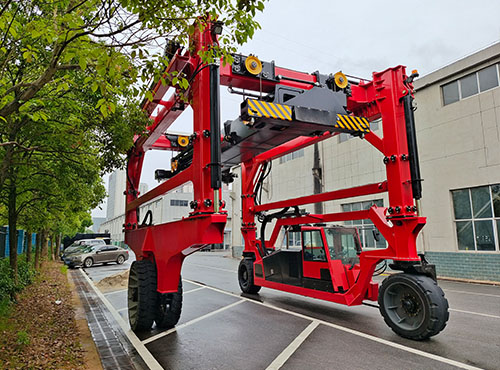
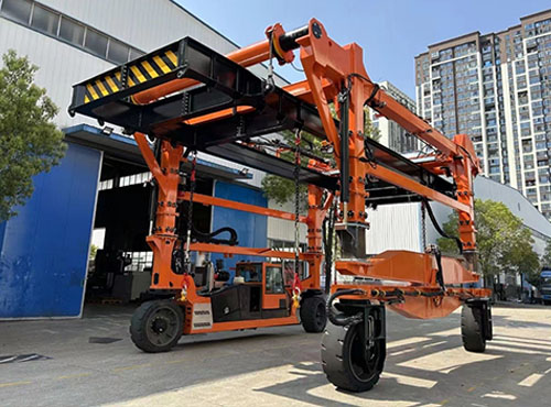
Unlike traditional container handling equipment, container straddle carriers feature a straddle-type gantry structure that allows containers to be positioned inside the vehicle body, where they are lifted and transported using specialized lifting attachments. The equipment does not require additional loading and unloading platforms during handling and can move flexibly between yards, loading and unloading areas, and various work sites.
In operational scenarios that require frequent handling of containers of various sizes, the structural design, powertrain configuration, steering system, and safety controls of a container straddle carrier all affect the equipment’s actual performance. These components are not independent of one another. Rather, they collectively determine the equipment’s load-carrying capacity, operational stability, and operational efficiency.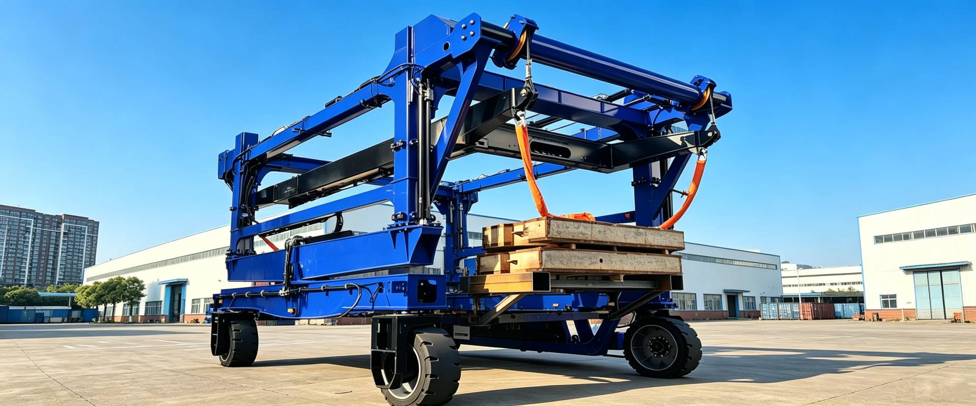
Container Straddle Carriers Structural Design
The structural design of container straddle carriers must focus on load-bearing capacity, equipment dimensions, and operational stability. Since containers are suspended inside the frame after being lifted, the overall structure must not only withstand vertical loads but also handle the dynamic forces generated during travel, steering, and braking.
Main Frame and Gantry Structure
The gantry structure must be designed based on the equipment’s rated lifting capacity, lifting height, and actual operating frequency. Once a container is lifted, its weight is transmitted through the lifting attachment and hoisting mechanism to the top beam, and then transferred via the uprights and bottom structure to the wheels and the ground.
During this process, the gantry primarily withstands the following forces:
- Vertical Loads: The primary load resulting from the weight of the container and its cargo.
- Dynamic Loads: Inertial forces generated when the equipment starts, stops, and accelerates.
- Lateral Loads: Lateral forces caused by turning, lateral movement, and uneven ground.
- Cyclic Stress: Fatigue loads generated by long-term, repetitive lifting and transport operations.
For equipment that requires prolonged continuous operation, it is not sufficient to consider only whether the frame undergoes significant deformation under maximum load; attention must also be paid to the performance of welded areas, beam-column connections, and other stress concentration zones.
Furthermore, the gantry structure height is closely related to the equipment’s stacking capacity. Therefore, the main gantry structure design must align with actual stacking requirements.
Lifting Mechanism and Spreader Support
The lifting mechanism is responsible for raising containers from the ground or a loading platform to the transport height. It is the key component connecting the gantry structure to the cargo.
Depending on the specific design of the container straddle carrier, the lifting mechanism may utilize a winch drive, wire rope transmission, or hydraulic lifting. Its main components include the lifting beam, drive unit, transmission components, and spreader connection mechanism.
During actual operation, the lifting mechanism must ensure that the spreader moves up and down along the set trajectory while controlling the lifting speed and stopping position. If significant asynchrony occurs during the lifting process, it may cause the container to tilt, subjecting certain structural components to additional loads.
The design of the lifting attachments also requires careful consideration. Container lifting attachments connect to the container’s corner fittings via twist locks, with common configurations including fixed and telescopic types. A reliable locking mechanism reduces the risk of connection failure prior to lifting, while position sensors help operators verify that the lifting attachments are in the correct position.
Wheel and Chassis Design
The wheels and chassis determine how the container straddle carrier supports its own weight and transfers the load to the ground. Since the equipment must move frequently under heavy loads, the wheels typically use large industrial tires, with the load rating determined based on the total vehicle weight and site conditions.
The chassis structure affects the vehicle’s wheelbase, turning radius, ground clearance, and tire load distribution. Container straddle carrier with longer wheelbases typically exhibit different driving and steering characteristics, while compact chassis are better suited for worksites with limited space.
The contact between the tires and the ground must also be taken into account. If the ground’s load-bearing capacity is insufficient, ground subsidence or localized excessive stress may occur—even if the equipment’s gantry structure and hoisting mechanism fully meet the rated load requirements.
Therefore, the design of the wheels and chassis must be considered in conjunction with the total machine weight, drive configuration, and on-site ground conditions.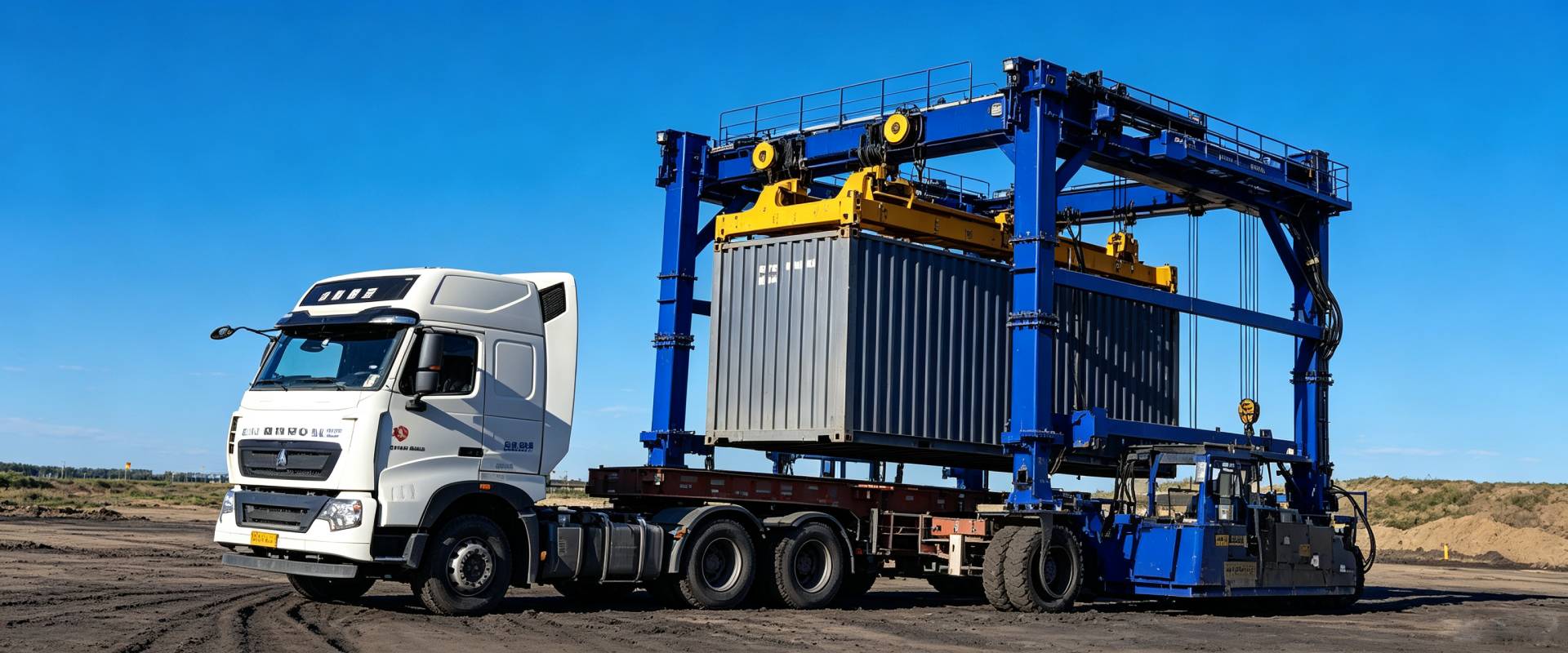
Core Systems Behind Container Straddle Carriers
Lifting System
The primary function of the lifting system is to grasp, lift, and lower containers. The process typically begins with positioning the lifting device. The operator uses the control panel to adjust the device’s position so that it aligns precisely with the container’s corner fittings.
During the lifting process, the system must coordinate the movements at each lifting point to prevent the container from tilting due to uneven force distribution. This is particularly important for heavier containers, as even a slight difference in height can cause the load to redistribute.
The lifting system’s stroke must also be tailored to the equipment’s operational environment. If the equipment needs to transfer containers between trailers or loading platforms at different heights, the lifting device’s working range must be calculated in advance.
Power System
The power system provides energy for the equipment’s travel and auxiliary mechanisms. Depending on project requirements, container straddle carriers typically employ diesel, electric, or hybrid power configurations.
A diesel power system generates power through an engine, which is then transmitted to the drive wheels via a transmission, drive shaft, or other drive mechanisms. This configuration is suitable for scenarios requiring extended operation, high-intensity work, and convenient access to fuel.
An electric system powers the drive motor via a battery. The motor can adjust output torque and rotational speed based on control commands, which helps reduce on-site exhaust emissions while also lowering operating noise.
However, for electric equipment, factors such as battery capacity, charging time, charging infrastructure, and continuous operating time must be considered. If daily working hours are long, the battery’s range under actual load conditions should also be evaluated.
Hybrid systems combine the advantages of different power types and are suitable for projects with comprehensive requirements regarding operating time, energy consumption, and emissions control.
Steering and Driving System
Container straddle carriers are large in size, and maintaining a certain safety clearance is necessary when handling containers. Therefore, the steering system directly affects the equipment’s maneuverability.
Common steering configurations include front-wheel steering, all-wheel steering, and crab steering.
Front-wheel steering primarily relies on the front wheels to change the direction of travel and is suitable for sites with wide aisles and relatively fixed travel routes. All-wheel steering allows multiple wheels to participate in steering, thereby reducing the turning radius. Crab steering allows the vehicle to move laterally or diagonally, offering certain advantages in areas with limited space.
The steering system is typically implemented through hydraulic mechanisms or electronic control units. For heavy-duty equipment, the steering process must not only ensure coordinated wheel angles but also account for friction between the tires and the ground, as well as lateral forces.
The drivetrain consists of drive wheels, brakes, suspension, and tires. Together, these components determine the equipment’s driving performance under both no-load and fully-loaded conditions.
Brake and Hydraulic System
The braking system is responsible for controlling the equipment’s deceleration and stopping. Under fully-loaded conditions, the machine’s inertia increases significantly; therefore, the braking system must be configured based on the maximum operating weight, travel speed, and operating conditions.
Braking performance not only affects stopping distance but also impacts operational safety on slopes and in turning areas.
The hydraulic system has an even broader range of applications. In addition to driving the mechanisms related to the extension, retraction, and lifting of the lifting gear, the hydraulic system also provides power for steering, clamping, and other auxiliary movements.
Stability of Container Straddle Carriers
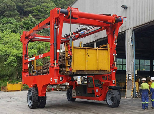
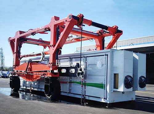
When handling heavy cargo, container straddle carriers must simultaneously cope with vertical loads, lateral forces, and variations in the ground surface. Stability is not a problem that can be solved simply by increasing the width of the equipment. Rather, it is determined by the wheel arrangement, lifting gear connection, suspension performance, and driving operations.
Wide Wheel Track
Container straddle carriers employ a structure supported by wheels on both sides, with the container located inside the frame. This arrangement creates a wide support area, providing a foundation for the vehicle’s lateral stability.
From a structural perspective, the wheel track affects the stability margin when the equipment’s center of gravity shifts laterally. As the load’s center of gravity gradually approaches the edge of the support area, the risk of the equipment tipping over increases.
Therefore, designers must comprehensively consider the wheel track, the equipment’s center of gravity, the maximum load, and permissible operating conditions, while operators must strictly adhere to the equipment’s specified operational limits.
Spreader
A spreader serves as the direct connection point between a container and the lifting equipment. It is typically attached to the container’s corner fittings via twist locks, allowing the container to be lifted and moved along with the equipment.
The reliability of the spreader’s connection directly affects the load conditions during the lifting process.
If the spreader is not fully aligned, or if a twist lock is not properly secured, uneven stress may occur in the container during lifting.
In addition, damage to the container’s corner fittings, cargo off-center loading, and deformation of the container itself may also affect lifting stability.
Therefore, before each operation, the condition of the container, the position of the spreader, and the locking status must be verified; one should not rely solely on the rated lifting capacity to determine whether lifting is permissible.
Suspension System
A multi-wheel configuration helps distribute the container straddle carriers’ total weight, but ground conditions experienced by different wheels during travel may vary.
The suspension system absorbs vertical shocks from the ground within a certain range and helps the wheels maintain contact with the ground. For heavy-duty container straddle carriers, a well-designed suspension system also helps control load distribution among the wheels.
Before selecting equipment, the work area should be surveyed to determine the ground’s load-bearing capacity, levelness, and slope requirements. These conditions not only affect equipment stability but also impact the service life of tires and chassis components.
Steering Control
When turning under heavy loads, the mass of the containers generates inertial forces, subjecting the equipment to additional lateral forces.
For example, when a piece of equipment is transporting a 40-metric-ton container, if it makes a tight turn at a high speed, both the container and the chassis will be subjected to greater lateral forces.
To manage this situation, it is necessary to select an appropriate travel speed and turning radius based on actual operating conditions, while avoiding sudden turns or frequent changes in direction.
For container straddle carriers equipped with multiple steering modes, precise coordination among the wheels is essential to prevent tire slippage or excessive lateral friction.
The stability of the equipment depends not only on the manufacturer’s structural design but is also closely related to the on-site road conditions and the operator’s driving habits.
Container Straddle Carriers Operating Process
The operating process of a container straddle carrier can be divided into five main stages: vehicle positioning, lifting device connection, lifting, transport, and container placement. Each stage has corresponding operational requirements; any deviation at any stage may affect subsequent operations.
Precise Positioning
When the container straddle carrier approaches the container to be transported, the operator must reduce speed and adjust the equipment’s direction based on the container’s position.
Once the container straddle carrier is positioned directly above the container, the operator must ensure that the mast fully spans the container and that the container is correctly positioned within the carrier’s frame.
This step requires particular attention to surrounding obstacles, the container’s position, and the equipment’s operating space. Accurate positioning reduces the need for repeated adjustments to the lifting gear and creates optimal conditions for the subsequent lifting operation.
Adjustment and Securing
After the container straddle carrier is properly positioned, the operator adjusts the length of the lifting device according to the container specifications so that the four corners of the lifting device align with the corner fittings of the container.
For telescoping lifting devices, the system can adjust the telescoping position based on the container type. Once the lifting device is lowered to the designated position, the twist locks engage with the corner fittings to secure the connection.
At this point, the locking status must be checked to confirm a secure connection and avoid lifting risks caused by positional deviations or lock malfunctions.
Steadily Lifting
During the lifting process, the operator must monitor whether the container remains level and whether all lifting mechanisms are operating normally. The lifting speed should not change abruptly. Particularly when first lifting off the support surface, attention should be paid to whether the container is subject to uneven loading or jamming.
Only after the container has been lifted to the specified transport height may the equipment proceed to the next phase.
Flexible Maneuvering and Travel
The container straddle carrier moves the container to the target area along a predetermined route. Depending on the available space and the equipment’s configuration, the equipment can adjust its position by driving in a straight line, turning, moving laterally, or traveling in a crab-walk pattern.
In work areas with narrow aisles, flexible steering methods can reduce the need for the container straddle carrier to make repeated U-turns.
However, speed must still be controlled during transport, and driving techniques should be adjusted according to the load height and ground conditions. In particular, when turning with a heavy load, sharp turns and sudden braking should be avoided.
Precise Positioning and Resetting
Upon reaching the target location, the operator must position the container within the designated area and then control the lifting mechanism to lower it slowly.
Only after the container has fully settled on the ground or the trailer’s loading surface, and stability has been confirmed, should the twist lock connection be released.
Subsequently, the lifting device rises and returns to its proper position, completing a full operational cycle.
Considerations for Selecting Container Straddle Carriers
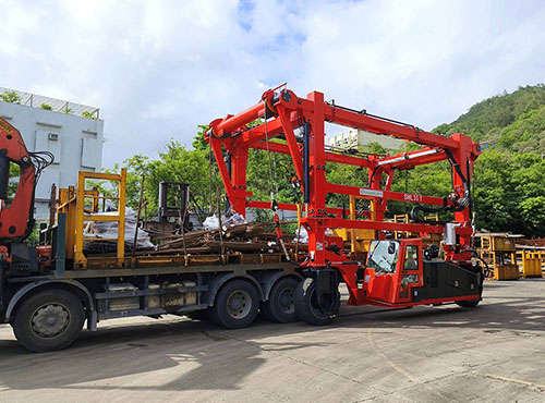
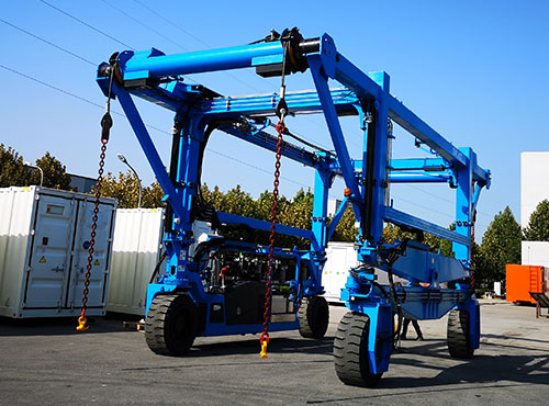
Container straddle carriers are large-scale specialized pieces of equipment. When purchasing them, their configuration must be determined based on actual operating conditions. Different projects have varying requirements for lifting capacity, stacking height, and mobility. Therefore, a model should not be selected based solely on the equipment’s appearance or a single parameter.
Lifting Capacity
The rated lifting capacity determines the maximum load the equipment can handle. The lifting capacity of common container straddle carriers typically ranges from 40 to 60 metric tons, though the specific requirement must be determined based on project needs.
When purchasing, the maximum total container weight must be clearly defined, and it is essential to verify whether the weight of the lifting attachments and other related components has been included in the rated load definition.
If the site involves heavy cargo, off-center loads, or special container types, further confirmation is required to ensure the equipment is suitable for these operating conditions.
Height and Spreaders
The lifting height determines the number of stacking levels the equipment can handle. Before purchasing, clarify the target stacking height and determine the mast height based on container dimensions and the work area.
Lifting attachments can be selected as fixed or telescopic depending on operational needs. If handling containers of various sizes is required, telescopic attachments typically offer a wider range of applicability.
Additionally, verify the attachment’s locking mechanism, adjustment range, and whether it features a status monitoring function.
Dimensions and Stability
The equipment’s overall width, length, and height must match the on-site aisles and operating space.
For example, when aisles are narrow, special attention should be paid to the equipment’s turning radius and lateral maneuverability. If containers need to be moved between higher levels, both the mast height and the machine’s center of gravity should be considered.
Speed and Acceleration
Travel speed directly affects the transfer time between different workstations. Some models can reach maximum speeds of 20 to 30 kilometers per hour, with specific values depending on the equipment configuration.
However, when purchasing, one should not focus solely on the maximum speed under no-load conditions; it is also necessary to understand the travel speed under full load, acceleration capability, braking performance, and turning speed limits.
For short-distance, high-frequency transport tasks, the equipment’s ability to operate smoothly under full load is equally important.
Drive System
Diesel, electric, and hybrid are common powertrain configurations.
Diesel power is suitable for scenarios with convenient fuel supply and extended continuous operation times. Electric power is better suited for projects with on-site emission and noise requirements and where charging facilities are available. For hybrid power, energy efficiency and maintenance costs must be evaluated in conjunction with specific operating conditions.
When selecting a model, comprehensively consider daily working hours, equipment operating frequency, energy prices, charging facilities, and the technical capabilities of maintenance personnel.
For equipment intended for long-term use, it is recommended to evaluate the purchase cost in conjunction with subsequent energy consumption and maintenance expenses.
